

what is an assembly drawing
We use cookies to ensure we give you the best experience on our website. You can find out about our cookies and how to disable cookies in our Privacy Policy. If you continue to use this website without disabling cookies, we will assume you are happy to receive them. Close.

Assembly drawing
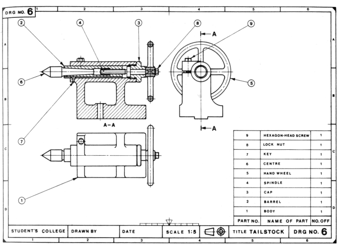
Assembly drawings can be used to represent items that consist of more than one component. They show how the components fit together and may include, orthogonal plans, sections and elevations, or three-dimensional views, showing the assembled components, or an exploded view showing the relationship between the components and how they fit together.
They may be used to show how to assemble parts of a kit such as furniture, how to assemble a complex part of a building (an assembly), or to show the relationship between a number of details.
The location of assemblies may be shown on general arrangement drawings, or sometimes on detail drawings. The components that form the assembly may be shown shop drawings that allow their fabrication.
Assembly drawings may include instructions, lists of the component parts, reference numbers, references to detail drawings or shop drawings, and specification information. However, they should not duplicate information provided elsewhere, as this can become contradictory and may cause confusion. They may also include dimensions, notation and symbols. It is important that these are consistent with industry standards so that their precise meaning is clear and can be understood.
Assembly drawings may be referred to as:
- General assembly drawings, showing an overall assembly.
- Outline assembly drawings, showing the exterior shape.
- Diagrammatic assembly drawings, representing the assembly with the use of symbols.
- Unit assembly or sub-assembly drawings, showing in more detail a part of the overall assembly.
- Fitted assembly drawings, showing the completed assembly.
- Exploded assembly drawing, showing the relationship between the separated parts.
The scale at which drawings are prepared should reflect the level of detail of the information they are required to convey. Different line thicknesses can be used to provide greater clarity for certain elements.
Assembly drawings may be drawn to scale by hand, or prepared using Computer Aided Design (CAD) software. However, increasingly, building information modelling (BIM) is being used to create 3 dimensional representations of buildings and their components.
BS EN ISO 7519:1997 Technical drawings. Construction drawings. General principles of presentation for general arrangement and assembly drawings establishes general principles of presentation to be applied to construction drawings for general arrangement and assembly. This standard compliments the ISO 128 series on technical drawings.
[edit] Find out more
[edit] Related articles on Designing Buildings Wiki
- As-built drawings and record drawings.
- Assembly.
- Building information modelling.
- Component drawing.
- Computer aided design.
- Concept drawing.
- Design drawings.
- Detail drawing.
- Drawings.
- Elevations.
- Engineering drawing.
- Exploded view.
- General arrangement drawing.
- Installation drawings.
- North American Paper Sizes
- Notation and symbols.
- Packaging.
- Paper sizes.
- Plumbing drawing.
- Production information.
- Projections.
- Scale drawing.
- Schematic.
- Section drawing.
- Shop drawings.
- Specification.
- Technical drawing.
- Technical drawing pen sizes.
- Working drawing.
what is an assembly drawing
Source: https://www.designingbuildings.co.uk/wiki/Assembly_drawing
Posted by: williamsherat1979.blogspot.com
0 Response to "what is an assembly drawing"
Post a Comment